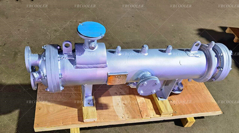
Shell Tube Type Drain Cooler in Condensate System
Condensate—water formed when steam releases its latent heat during heating or power generation—is a valuable resource: it is already demineralized (critical for boiler feedwater) and retains significant sensible heat (typically 100–250°C, depending on the steam system pressure). A shell-and-tube drain cooler addresses two critical needs:
Heat Recovery: Extracts sensible heat from hot condensate to preheat colder streams (e.g., makeup water, boiler feedwater) or other process fluids, reducing energy consumption for heating.
Condensate Pre-Cooling: Lowers the temperature of hot condensate to a safe, manageable level (often 40–80°C) before it enters condensate pumps or storage tanks. This prevents pump cavitation (caused by high-temperature water vaporizing at the pump inlet) and extends equipment lifespan.
The drain cooler operates on the countercurrent heat exchange principle (the most efficient flow arrangement for this application), where the hot and cold fluids flow in opposite directions. Here’s a step-by-step breakdown:
Hot Condensate Inlet: High-temperature condensate (e.g., 180°C from a steam turbine) enters the shell side of the cooler through the shell inlet nozzle.
Turbulent Flow via Baffles: As the condensate flows through the shell, baffles force it to zigzag around the tube bundle. This turbulence maximizes contact between the hot condensate and the cold tube surfaces, enhancing heat transfer.
Heat Transfer to Service Fluid: The cold service fluid (e.g., 25°C makeup water) enters the tube side via the inlet header, flows through the tubes, and absorbs heat from the shell-side condensate.
Countercurrent Flow Advantage: Since the hot condensate and cold service fluid flow in opposite directions, the temperature difference between them remains large across the entire length of the exchanger. This ensures maximum heat recovery (e.g., the service fluid may exit at 80–120°C, while the condensate cools to 50–70°C).
Fluid Exit:
Cooled Condensate: After releasing heat, the condensate drains from the shell’s bottom outlet (via a steam trap or control valve) and is sent to a condensate tank or boiler feedwater system.
Preheated Service Fluid: The now-warm service fluid exits the tube-side header and is directed to a boiler, heater, or other process that requires heated water—reducing the energy needed to reach its target temperature.
Applications in Condensate Systems
Power Plants: Cools condensate from steam turbines before it enters deaerators (which remove oxygen to prevent boiler corrosion) and preheats boiler feedwater.
Food & Beverage Industry: Cools condensate from steam-heated process equipment (e.g., pasteurizers, cookers) to avoid damaging pumps and preheats makeup water for boilers (critical for maintaining food safety, as demineralized condensate is hygienic).
Chemical & Petrochemical Plants: Recovers heat from condensate in reactor cooling or distillation processes, while pre-cooling condensate to protect pumps in hazardous fluid loops.
Commercial Buildings: Cools condensate from HVAC steam heaters or domestic hot water systems, preheating cold water to reduce energy use for water heating.


