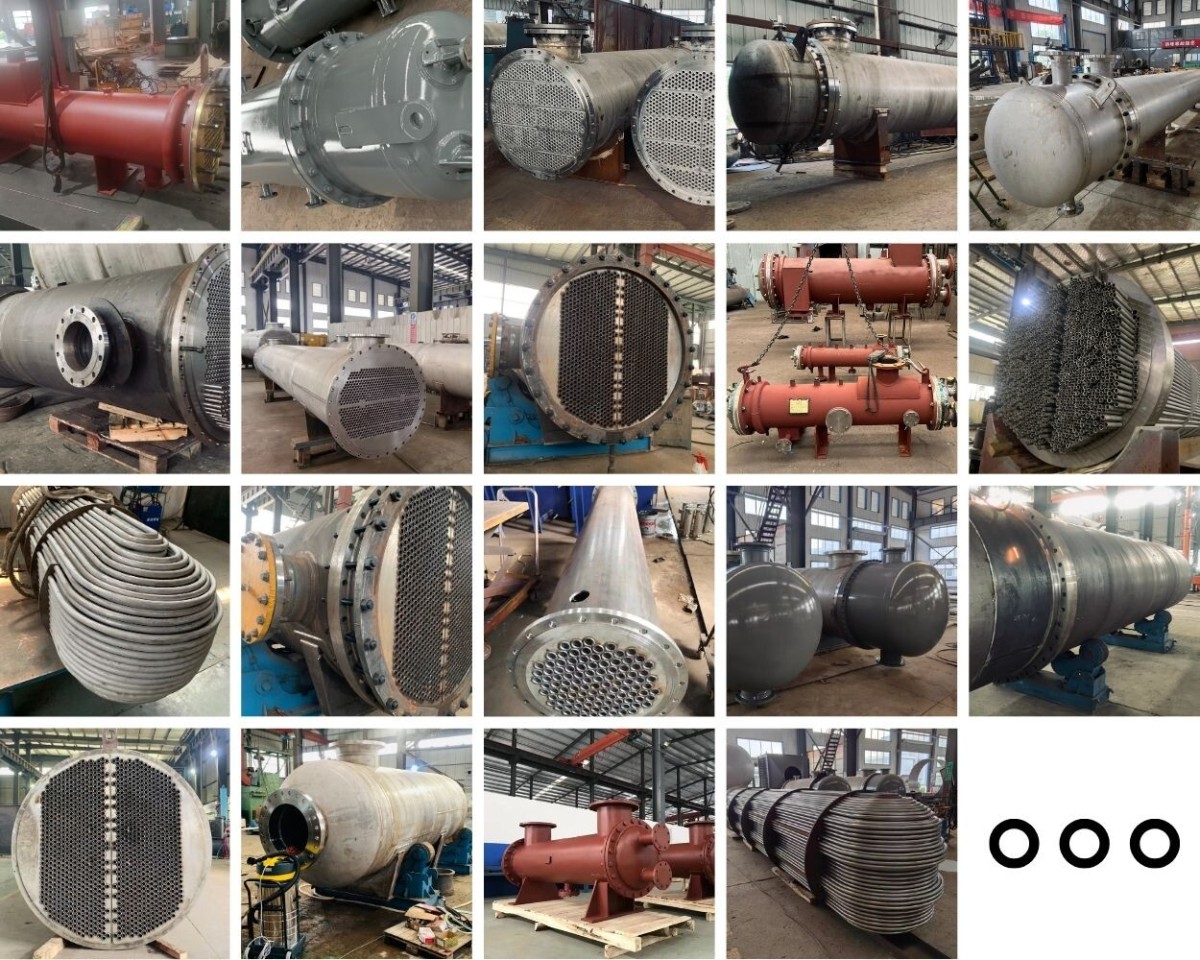
Designing a shell and tube heat exchanger involves several steps:
1. Determine Process Requirements:
Identify the fluids to be heated or cooled, including their flow rates, inlet and outlet temperatures, physical properties (density, viscosity, specific heat, thermal conductivity), and pressure limits.
Determine the heat transfer duty (amount of heat to be transferred) based on the process needs.
2. Select Tube and Shell Materials:
Consider factors such as corrosion resistance, compatibility with the fluids, temperature limits, and mechanical strength.
Common materials for tubes include copper, stainless steel, and various alloys. The shell can be made of carbon steel, stainless steel, or other suitable materials.
3. Decide on Flow Arrangement:
Determine whether the hot and cold fluids will flow on the tube side and shell side. Consider factors such as heat transfer coefficients, pressure drop, fouling potential, and ease of maintenance.
Options include countercurrent flow (most efficient for heat transfer), co-current flow, or a combination.
4. Calculate Heat Transfer Coefficients:
Estimate the heat transfer coefficients for both the tube side and shell side fluids using empirical correlations or software.
Consider factors such as fluid velocity, viscosity, and tube geometry.
5. Determine Surface Area and Tube Count:
Use the heat transfer duty, overall heat transfer coefficient (calculated from tube and shell side heat transfer coefficients), and temperature differences to determine the required surface area.
Based on the surface area, select an appropriate tube diameter and length and calculate the number of tubes needed.
6. Design the Shell:
Determine the shell diameter based on the tube bundle size and allow for proper clearance.
Select baffles or support plates to enhance heat transfer on the shell side and support the tubes.
Design the shell nozzles for fluid inlet and outlet.
7. Calculate Pressure Drop:
Calculate the pressure drop on both the tube side and shell side to ensure that it is within the allowable limits of the process.
Adjust flow rates or tube geometry if necessary to meet pressure drop requirements.
8. Check Mechanical Design:
Ensure that the heat exchanger can withstand the operating pressures and temperatures.
Check for mechanical integrity, including tube-to-tubesheet joints, shell thickness, and support structures.
9. Perform Thermal and Hydraulic Analysis:
Use software or analytical methods to verify the heat transfer and pressure drop calculations.
Optimize the design if necessary to improve performance.
10. Documentation and Fabrication:
Prepare detailed design drawings, specifications, and operation manuals.
Select a reputable manufacturer to fabricate the heat exchanger according to the design.
Designing a shell and tube heat exchanger requires a combination of engineering knowledge, experience, and the use of appropriate software and tools. It is important to follow industry standards and best practices to ensure a safe and efficient design.


